The
U-Config Configuration
utility

This
utility is used for the following:
-
Assigning
a board number (1-8) if you have multiple boards.
-
Configuring
each pin of the board as the correct device type, ie keyboard, gamepad,
analog, quadrature mouse, power.
-
Configuring
each pin with the correct keycode, button number, axis or other
parameter
-
Assigning macros
-
Configuring analog axis scale factor
and offset
-
Loading
and saving configurations
-
Initiating
a firmware upgrade
-
Downloading
a configuration "on the fly" using a command-line task
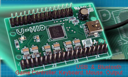
The
graphical picture of the board shows the way in which the pins are
divided into sections, each being one 9-pin connector (plus key). Pin 1
is the key and pin2 is ground.
The
utility interacts with the board in real time, every time a change is
made.
The
configuration is stored in flash ROM on the board so it remains after
power off/on.
When
the utility is run, it reads the configuration from the connected
board(s) and displays it.
You can also store the entire configuration as a file for later
downloading on-the-fly for multiple configurations.
Function
of each GUI feature:
GENERAL
tab (main window)
PIN
drop down
This
displays the selected pin you
are configuring. You can select pins from here or from the main graphic.
NICKNAME
You can type text in here which will
remind you of which device this pin is connected to. The test is saved
with the configuration (on the PC only) and is not sent to the board.
FUNCTION area
Here
you configure the selected pin
as the required device type and assign values to it.You
can select one of the radio
buttons to define the pin as the following:
Switch
(which includes keyboard
key, gamepad button and mouse buttons)
Quadrature
Mouse (includes trackballs,
optical steering wheels etc)
Analog
(Gamepad type control)
LED
output (includes U-HID and
PC Controlled)
+5
Volts out (max 30 ma)
Ground.
APPLY
This button applies the changes you
have made to the pin.
GRAPHIC
AREA
You
can click on any pin on the
graphic to start configuration of this pin. Additionally,
if you click on the pin
types listed in the center of the PCB, this will show which pins are
allowed to be configured as this type of control.You
will notice that certain pins on
P7 are fixed. These are high-current power/ground pins and are
hard-wired and cannot be changed.Each
10-pin connector area has one
hard-wired ground pin.
CALIBRATION
tab
This tab allows you to set scale factor and offset for each analog
input. The default values give a full-scale travel with the cross-hair
centered at mid-position of the pot. It may be necessary to experiment
with these settings and you can observe the result by opening Control
Panel, Game Controllers in Windows, and clicking on the came controller
device to display the calibration screen.
In addition the Calibration tab also contains the setting for
Quadrature Button press time (U-HID Only). This is the length of time
(actually the number of USB packets) which the game controller button
is pressed for when using Quadrature Buttons. This is a global setting.
On the BlueHID board, Power Saving
mode configuration is set here. Refer to the BlueHID manual for full
details of power saving features.
Disconnect
Timeout
The slider defines how many seconds
of no-activity elapse before the board disconnects the Bluetooth link.
Or you can opt to have the board never disconnect but this will consume
more battery power
Wake Any Pin
button
After disconnection, the board will wake and re-connect if
activity is detected on any pin which is defined as a switch.
Wake
J2-6 Only Button
When this is selected, the board will only wake when activity is
detected on pin J2-6. In this mode (Stop Mode) the board is in maximum
power-saving state.
Self-Test LED The self-test on-board LED can be disabled. This is
recommended after testing is complete, to conserve power.
Detail Configuration Example (Switch)
The
screenshot above shows this
configuration.
We will look at how a switch is connected and configured.
Firstly, the switch is connected
with
one terminal routing to the appropriate pin and the other to a ground
pin.
Then, select the pin by clicking
on
it in the graphic area.
Select the "Switch" radio button
in
the Function area.
You now need to select what type
of
control this will be, whether a mouse button, keyboard key or gamepad
button. Lets select keyboard key.
In the Primary drop-down, all
possible keyboard keys will be available, plus macros. Macros are
defined separately, see later.
Select which keyboard key you need. Note that the U-HID sends key
scan
codes, just like a keyboard. It does not send characters so has no
concept of upper/lower case. An upper-case character is two keys (ie
shift and the character key). There is no need to assign a
secondary code unless you wish to use the shift feature or other
special functions, see later.
Then, you need to tell the board
how
and when to send the keycode you have chosen. This is done with the
Down and Up Action drop downs. These can be selected as follows:
Clear
This removes the keycode
associated with this pin from the buffer, so it is no longer sent
Normal
Primary
This sends (and holds) the
primary keycode you selected above, to the PC. If the U-HID Shift
button is pressed, it will send the secondary code instead.
Normal
Secondary
This sends (and holds) the
secondary keycode but you have not assigned one at this point so no
action.
Pulse
Primary
This sends a short pulse,
simulating the key being pressed then released, even though it might
still be physically closed (eg a toggle switch left closed)
Pulse
Secondary
This is the same as above but
pulses the secondary code.
Toggle
This is not explicitly an
option, but is the result of setting both the Down and Up actions to
Normal Primary. This will cause the selected keycode to alternately be
sent or not sent on alternate button presses.
Flip-Flop
This is not explicitly an
option but is the result of setting Down action to Secondary and Up
action to Primary. This will cause the primary or secondary key to be
sent on alternate button presses.
See-Saw
This is not explicitly an option but
is the result of setting Down action to Primary and Up action to
Secondary. This will cause the primary key to be sent on press and
secondary on release. Normal or Pulse mode can be used.
The
most common usage of keyboard keys is to set Down Action to Normal
Primary and Up Action to Clear.
Important
Note about keyboard keycodes:
On USB keyboards (and therefore the U-HID) the auto-repeat of the
keyboard is done in Windows. So if you assign any keycode to be pressed
permanently (which can occur in many configurations) you will get an
endless string of characters in your application. For this reason, many
of the advanced combinations should only be used with gamepad buttons,
which do not have a problem being held in the pressed position.
You should also avoid
defining any keyboard keys from being "pressed" by default as this will
cause boot failures (stuck key) and may cause unexpected problems in
the Windows GUI.
Other
switch types:
Mouse
Button
You can select left, middle,
right and left double-click from the drop-down.
Gamepad
Button
These are numbered 1-32 as
shown in "Control Panel, Game Controllers".
Quadrature
Mouse Selection
This
selection always uses two pins.
When you assign the pin as this device type, the opposite pin will also
automatically be assigned.
You can select X, Y or Z (wheel)
axis.
Trackballs use two axes (4 pins).
Quadrature
Button Selection
This selection uses two
pins. When you assign the pin as this
device type, the opposite pin will also automatically be assigned.
You can select one of 8 pairs of game controller buttons which will be
pressed repeatedly when the encoder is turned. Note you can configure
the "press" time on the Calibration tab.
Analog
Axis
These are
numbered 1-8. You can view
analog axes using Control Panel, Game Controllers.
The first two axes are displayed as X and Y.
LED
There are
two types of LED.
U-HID
controlled (switch)
This type of LED is switched
on when the switch allocated to it is sending its keycode or button
(which might not necessarily mean the switch is physically closed,
depending on how the switch pin is configured).
In the drop-down, you can select which switch (referenced by its pin)
controls this LED.
PC
Controlled LED
This type of LED is switched
on/off by a PC application. These are numbered 1-16.
Other Functions
FILE
menu
Open,
Save
These
selections allow loading/saving
of .HID configuration files, so you can have multiple saved
configurations.
Import/Export
You can
import and export
configurations to a CSV or XML file so you can edit them outside of the
application or generate using a different application.
Assign
ID
This is an
important first step when
you are using more than one board. You will need to connect ONE board,
and assign it as number 2 or higher. Once all boards are assigned with
different IDs, they can all be connected to their own USB ports. You
can check which board is which by opening Control Panel, Game
Controllers. The board ID# is displayed a the top of each Game
Controller window.
Firmware
Upgrade
This
initiates a firmware upgrade.
The board assumes a different USB ID and a driver will be installed.
Details will be included with firmware.
VIEW
menu
There is
only one option, "View U-HID Shift Option". This is normally hidden in
the main area to avoid clutter.
This is only used when assigning a pin to be a U-HID shift key.
The
shift option allocates a key (or keys) which, when held, cause other
pressed keys to send their secondary instead of primary keycodes. This
over-rides the Primary/Secondary Action defined for keys.
|